
OP3
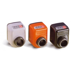
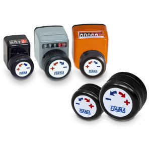
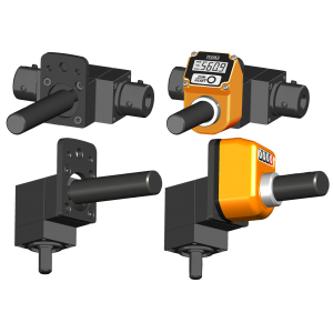
Position indicator with hollow shaft

• 4 digits counter (standard red digit indicates decimals; on request 2 red digits for hundredths or 4 black digits for mm). Reading until 9999.Digit height 5 mm
• Shock-proof self-extinguishing technopolymer. Protection IP64. Max. temperature 80°C.
• Reading with inclined 18° or frontal view.
• Standard shaft bore: ø14H7; other bores, smaller than 14 with reducing bush.
On request:
• Special ratios and measures in Inches.
• Lock pin “P6” ø6 mm or “c” ø9/10,5.
• Model “IN” with metallic parts in stainless steel.
• Colours: orange RAL 2004, black RAL 9005, grey RAL7004.
• Combinable tools: flanged gearbox: RINV-OP64 (see drop-down menu on the right).
• Available accessories: shaft block flange, spacer flange, movement knob, handle, handwheel (see drop-down menu on the right).
Photogallery


1. Hollow shaft Ø14
2. Fixing screw
3. Lock pin
4. 2 Ø2,5x5 fixing holes
5. Dust seal
6. Lock pin ø 9/10,5
7. Lock pin Ø 6
| MOUNTING POSITION | |||
 |
 |
 |
|
| VIEW «A» for horizontal shaft tilted, top view |
VIEW «B» for vertical shaft, side view |
VIEW «C» for horizontal shaft, low front view |
VIEW «D» for horizontal shaft, top front view |
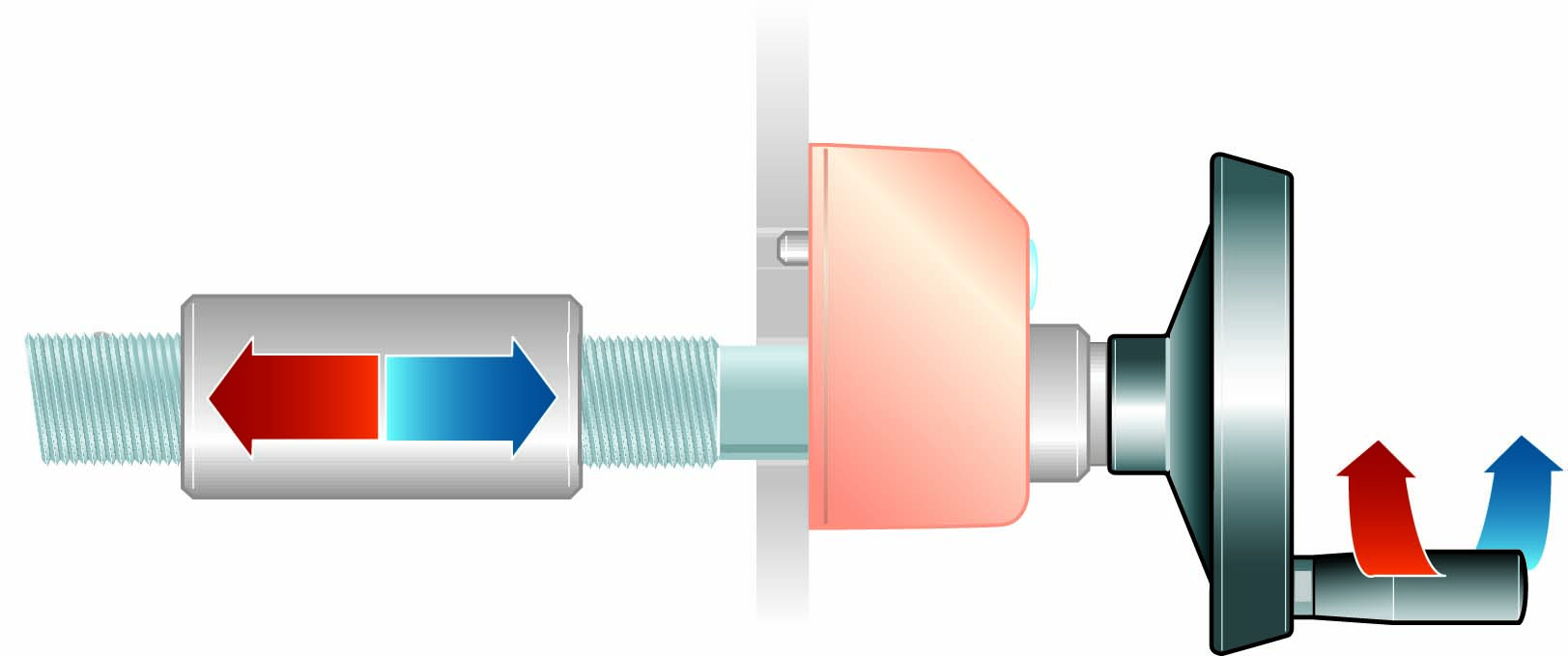
| Introduce the indicator through the hollow shaft and set the lock pin into the arranged hole. Set the instrument on the inner (zero) value and block the fixing screw. | |||

| DISPLAY | |
 |
for decimal indication (standard) |
 |
for hundredths indication (2RR) |
 |
for millimeters indication (4RN) |
|
DIRECTION OF ROTATION |
| DX increasing values with clockwise rotation, decreasing values with anti-clockwise rotation |
 |
| SX increasing values with anti-clockwise rotation, decreasing values withclockwise rotation |


Reducing technopolymer bushes for OP.
➜ for more complete information, see BF

Reducing bushes for shaft block flange OP (technopolymer).
➜ for more complete information, see BF-BL

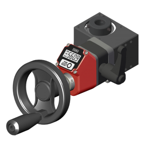
Control handwheel with folding handle, thermoplastic material, steel bush.
➜ for more complete information, see V.R

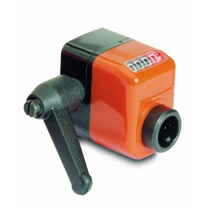
Crank handle with folding handle in thermoplastic material, steel bush.
➜ for more complete information, see V.M

The motion-knob is directly assembled on the shaft of the indicators OP2, OP3, OP6, OP6F25, OP6, OP6F25.
On request stickers (neutral or with Fiama logo), which on the motion-knob’ s front shows the increase or decrease of measure wise.
Material: anodized aluminium.
➜ for more complete information, see PM
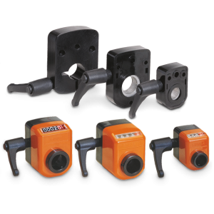
With the shaft block flange on the OP2, OP3, OP6, OP7, OP5, OP9 indicator as a compact unity, we obtain a safe blocking of the drive shaft.
➜ for more complete information, see FL-B

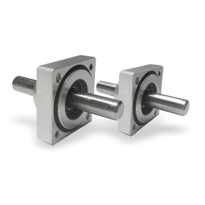
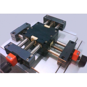
Flanged supports with extension shaft for coupling with position indicators.
➜ for more complete information, see Flanged supports


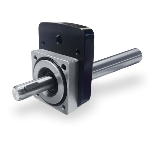
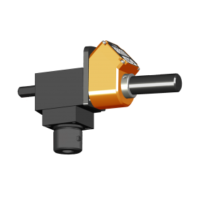
Compact reducer with high-performance, complete with fixing flange and extension shaft for display with ‹OP2/OP3› position indicator.
➜ for more complete information, see RD26 FL-OP2/OP3/EP3
Compact reducer with high-performance, complete with fixing flange and extension shaft for display with ‹OP3› position indicator.
➜ for more complete information, see RD40-FL-OP3/EP3
Compact reducer with high-performance, complete with fixing flange and extension shaft for display with ‹OP3/EP3/OP7/EP7› position indicators.
➜ for more complete information, see RD50 FL-OP3/EP3/OP7/EP7
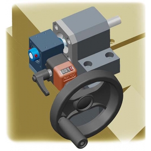
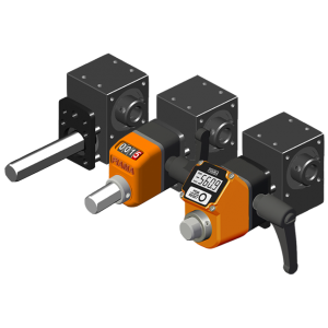
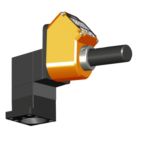
Angular gearbox 66/4 with flange MØ14x68 FL-OP3/EP3, designed for connection with the position indicator. It ensures precise adjustments and accurate monitoring of the position, enhancing stability and reading accuracy. The flange, made of black anodized aluminum, perfectly matches the gearbox case, both featuring the same elegant and durable finish.
➜ for more complete information, see 66/4

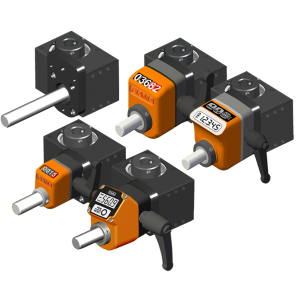
Angular gearbox 66/5 with flange MØ14x68 FL-OP3/EP3 and MØ14x80 FL-OP7/EP7, designed for connection with the position indicator. It ensures precise adjustments and accurate monitoring of the position, enhancing stability and reading accuracy. The flange, made of black anodized aluminum, perfectly matches the gearbox case, both featuring the same elegant and durable finish.
➜ for more complete information, see 66/5
Photogallery


Richiedi l'accesso


INDICATION AFTER 1 REVOLUTION
1R = 1 red digit (decimals)
2RR = 2 red digits (hundreths)
4RN = 3 cifre nere (millimeters)
(") = indication in inches
Vmax = referred to decimal indication (0,1)
Vmax" = referred to indication in inches
| 1R | 2RR | 4RN | (") | Vmax | Vmax" |
|---|---|---|---|---|---|
| 0,1 | 0,01 | mm | inches | rpm | rpm |
|
0005 |
0005 |
0005 |
600 |
||
|
0050 |
0050 |
0050 |
200 |
||
|
0007(5) |
0007(5) |
0007(5) |
600 |
||
|
0010 |
0010 |
0010 |
0039(37) |
800 |
200 |
|
0012(5) |
0012(5) |
0012(5) |
800 |
||
|
0015 |
0015 |
0015 |
600 |
||
|
0017(5) |
0017(5) |
0017(5) |
600 |
||
|
0020 |
0020 |
0020 |
0078(74) |
500 |
200 |
|
0025 |
0025 |
0025 |
500 |
||
|
0030 |
0030 |
0030 |
0011(81) |
300 |
600 |
|
0040 |
0040 |
0040 |
0015(74) |
300 |
500 |
|
0050 |
0050 |
0050 |
0019(68) |
200 |
500 |
|
0060 |
0060 |
0060 |
200 |
||
|
0075 |
0075 |
0075 |
200 |
||
|
0080 |
0080 |
0080 |
100 |
||
|
0100 |
0100 |
0100 |
0039(37) |
100 |
200 |
|
0120 |
0120 |
0120 |
80 |