FL-B
Shaft block flange OP2 - OP3 - OP6 - OP7 - OP5 - OP9
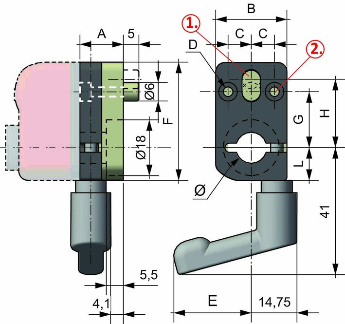
With the shaft block flange on the OP2, OP3, OP6, OP7, OP5, OP9 indicator as a compact unity, we obtain a safe blocking of the drive shaft.
Handle in position “a” or “b”.
Block component in anodized aluminium.
• Available stainless steel flange in model FL-B OP3, bore ø14.
| FLB-OP2 | FLB-OP3 | FLB-OP6 | FLB-OP7 | FLB-OP5 | FLB-OP9 |
 |
 |
 |
 |
 |
 |
| BORE DIAMETER | |||||
| ø 8 | ø 14 | ø 14 | ø 14 | ø 20 | ø 20 |
| ø 10 | ø 10 | ø 20 | ø 20 | - | ø 25 |
| ø 12 | - | ø 25 | ø 25 | - | - |
| other bores with reducing bushes | |||||
| OP2 |

1. Bore for lock-pin Ø6
2. 2 fixing bores
3. Embedding ø17x1
| Type | Dimension | |||||||||
| Ø | A | B | C | D | E | F | G | H | L | |
| OP2 | 8-10-12 | 14 | 23 | 7,5 | ø 3,1 | 25 | 38 | 18 | 22 | 10,5 |
| OP3 - OP6 - OP7 |

1. Bore for lock-pin Ø6
2. 2 fixing bores Ø
| Type | Dimension | ||||||||||
| Ø | A | B | C | D | E | F | G | G1 | H | L | |
| OP3 | 14-10 | 15 | 32 | 10 | ø 4,2 | 50 | 46 | 20 | - | 22 | 16 |
| OP6 - OP7 | 20-14 | 15 | 48 | 18 | ø 4,2 | 50 | 66 | 25 | 19,5 | 30 | 24 |
| OP5 - OP9 |

1. Bore for lock-pin Ø6
2. 2 fixing bores
| Type | Dimension | ||||||||||
| Ø | A | B | C | D | E | F | G | G1 | H | L | |
| OP5 | 20 | 18 | 52 | 18 | ø 4,5 | 57,5 | 74 | 20 | - | 30 | 25 |
| OP9 | 20-25 | 18 | 64 | 18 | ø 4,5 | 64 | 94 | 25 | 40 | 30 | 25 |

Reducing bushes for shaft block flange OP (technopolymer).
➜ for more complete information, see BF-BL

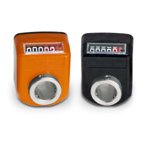
• 4 digits counter (standard red digit indicates decimals; on request 2 red digits for hundredths or 4 black digits for mm). Reading until 9999.Digit height 5 mm
• Standard shaft bore: ø14H7; other bores, smaller than 14 with reducing bush.
➜ for more complete information, see OP3

• 3 digits counter (standard red digit indicates decimals; on request 2 red digits for hundredths or 3 black digits for mm). Reading until 999. Digit height 6 mm
• Particularly suitable for little adjustments in small spaces.
• Standard shaft bore Ø8, Ø10 or Ø12.
➜ for more complete information, see OP2

• 5 digits counter (standard red digit indicates decimals; on request 2 red digits for hundredths or 5 black digits for mm).
• Readings until 99999. ‘Lens to improve the reading’: digit height 7 mm.
• Standard shaft bore ø20 (OP7) or ø25 bore (OP7F25). Other holes smaller than 20 with reducing bush.
➜ for more complete information, see OP7

• Measures linear or angular movements, applicable to many types of industrial
• Simple assembly through the hollow shaft
• Powered by long battery life, easy replacement from the front
➜ for more complete information, see EP7

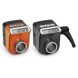
The EP3 electronic indicator allows monitoring of adjustments to eliminate errors and a precise reading of linear or angular displacements.
• 100% interchangeable with mechinal indicator OP3.
• Powered by a long-life battery, easy replacement from the front.
• Hollow shaft made of stainless steel; shock, vibration and dirt resistant plastic case.
➜ for more complete information, see EP3

• 5 digits counter (standard red digit indicates decimals; on request 2 red digits for hundredths or 5 black digits for mm).
•OP6 a standard shaft bore ø20H7, version OP6F25 with ø25 bore. Other holes smaller than 20 with reducing bush.

• 5 digits counter (standard red digit indicates decimals; on request 2 red digits for hundredths or 5 black digits). Model OP9T: 4 digits with graduated digit. Readings until 99999. Digit height: 7 mm.
• OP9 standard shaft hole ø20 or ø30, version OP9F35 hole ø35, different holes with reducing bush.
➜ for more complete information, see OP9
• 5 digits counter (standard red digit indicates decimals; on request 2 red digits for hundredths or 5 black digits). Readings until 99999. Digit height mm 5,5
• It is possible to reverse the counting direction ratios from «pitch 1 to pitch 15».
• Standard shaft hole: ø20 H7; different holes smaller than 20 with reducing bush.
• Model “AZZ” with button for positioning and zero-setting, with 4 digits counter, in ratios from «pitch 1 to pitch 6».
➜ for more complete information, see OP5


