
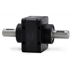
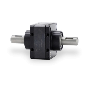
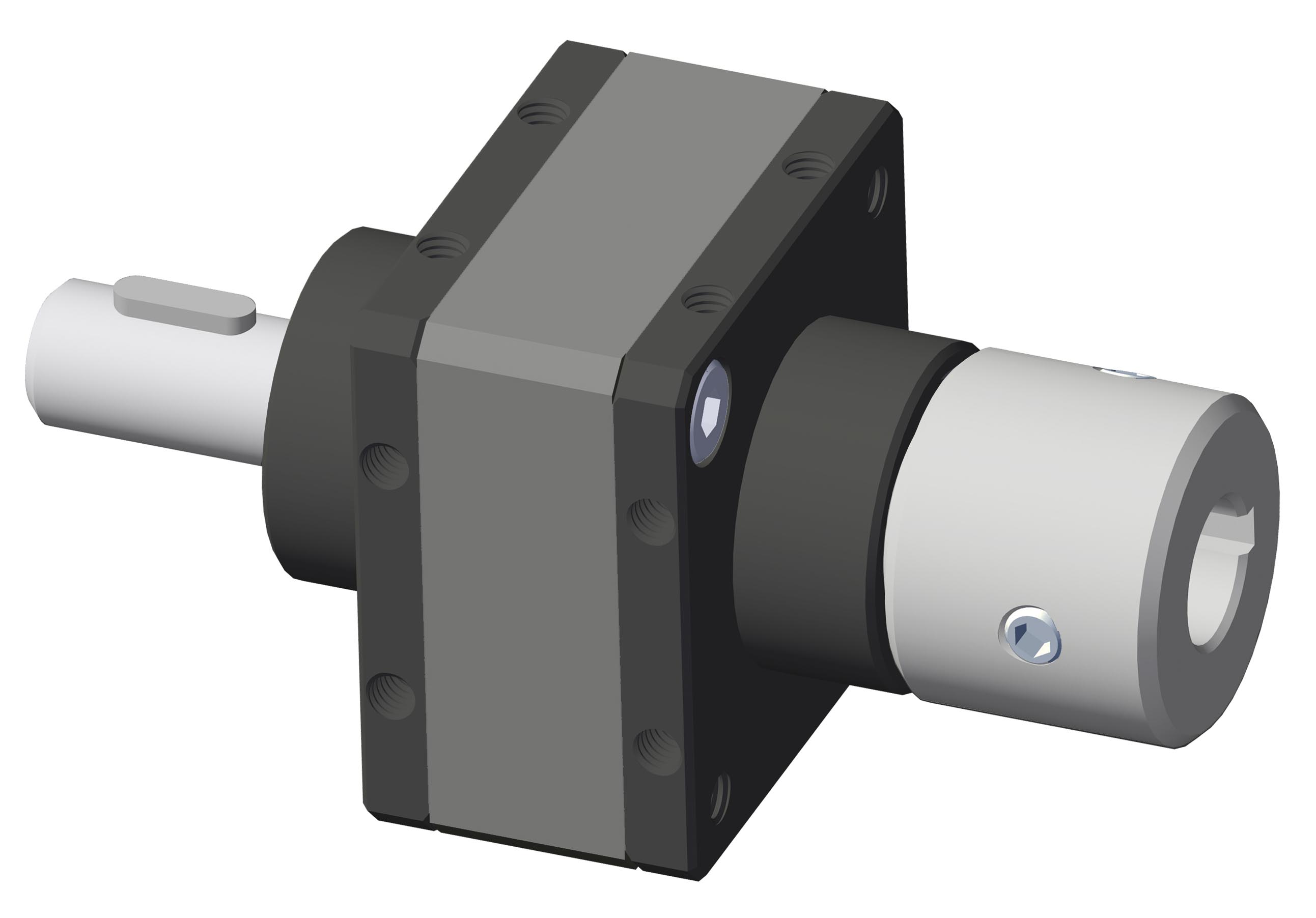
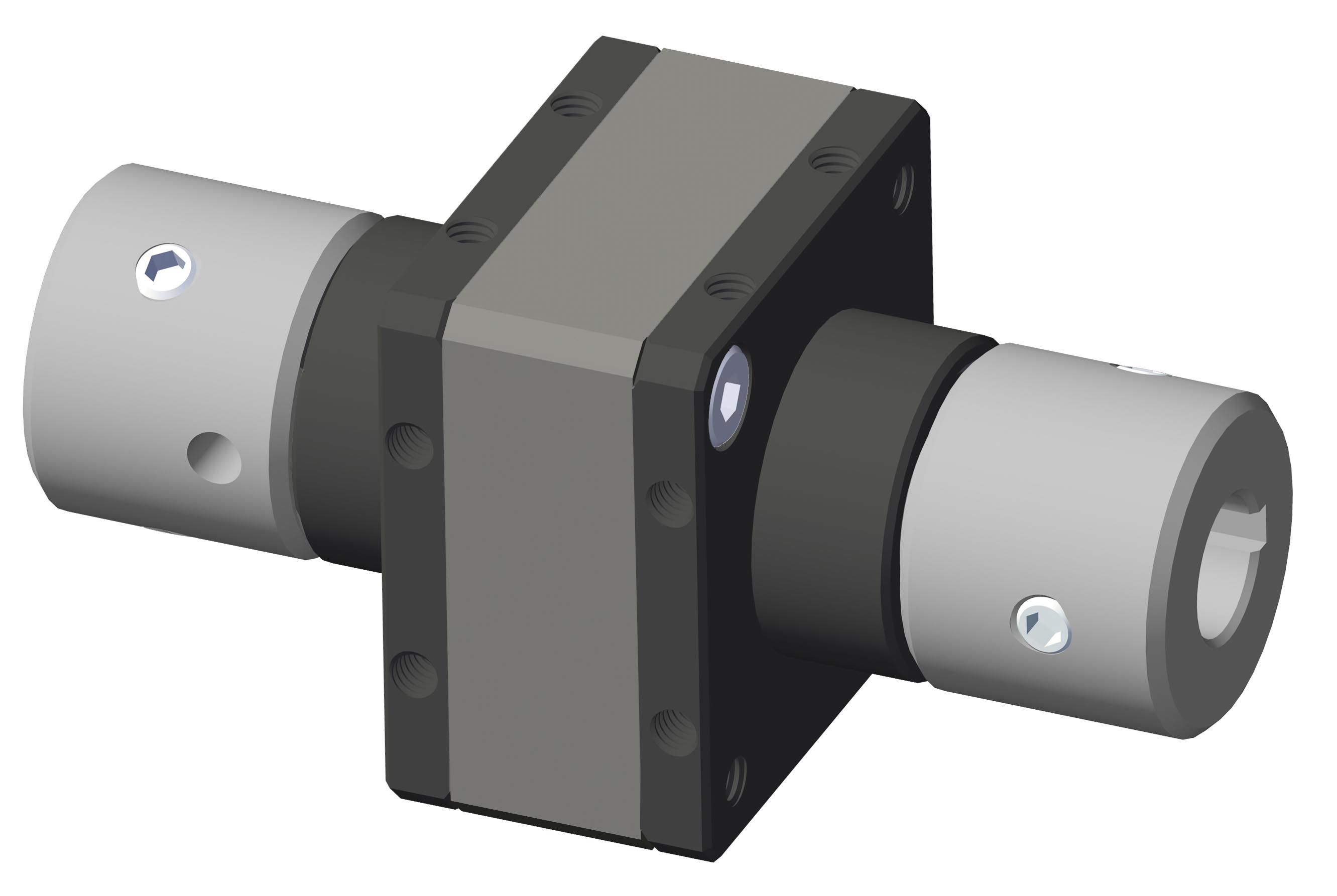
RDE40
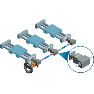
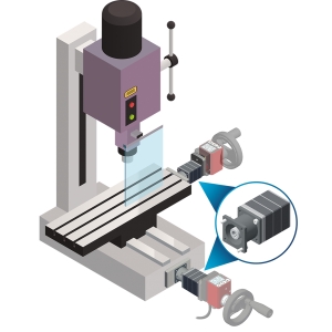
Coaxial planetary reducers
| ● High torque transmission with minimal dimensions. |
| ● Speed reduction and torque increase. |
| ● Transmissibile torque 20 Nm. |
| ● Single- or multi-stage (up to 3) with a wide choice of reduction ratios: the modular system combines the advantages of standardization with a high degree of customization. |
| ● Aluminum housing (surface treated) and stainless steel shafts AISI303. |
| ● In the UC version (for continuous use), lubrication is oil bath for speeds above 200 rpm and grease for speeds of 200 rpm or lower. |
| ● Silent operation, reliability and high performance |
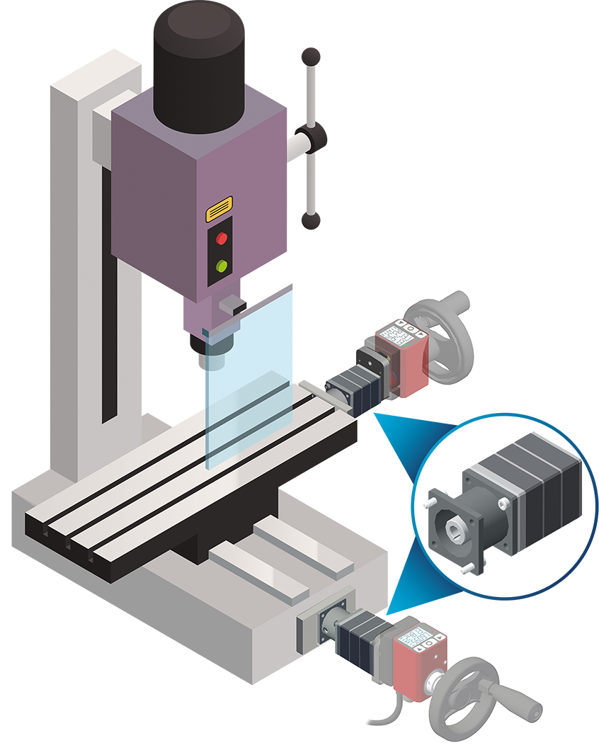
| ● Can be mounted horizontally and vertically. |
| ● Clockwise DX and counterclockwise SX rotation for alternating and continuous operation. |
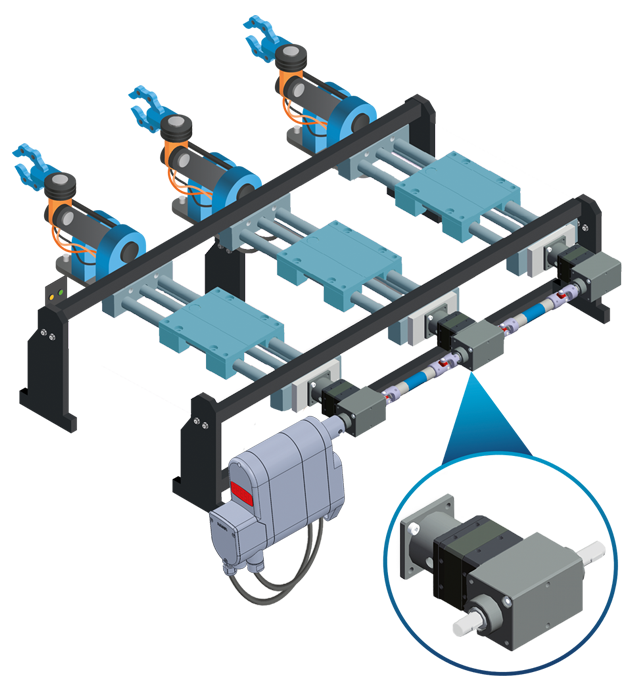
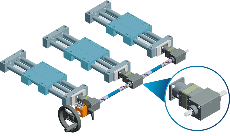
| ● Various mounting possibilities with male shafts (plain or with key), female shafts with fixing screws, flanges for direct coupling and display with "OP3 - OP7 - EP7" position indicator. |
Photogallery


| RDE40 | ||
|
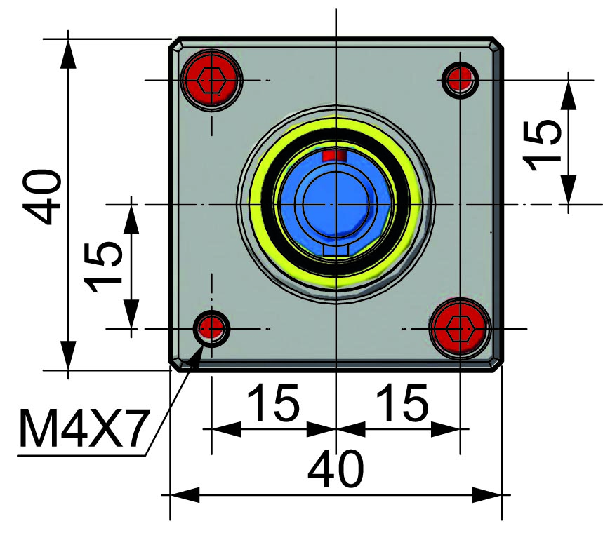
bottom view |
 |
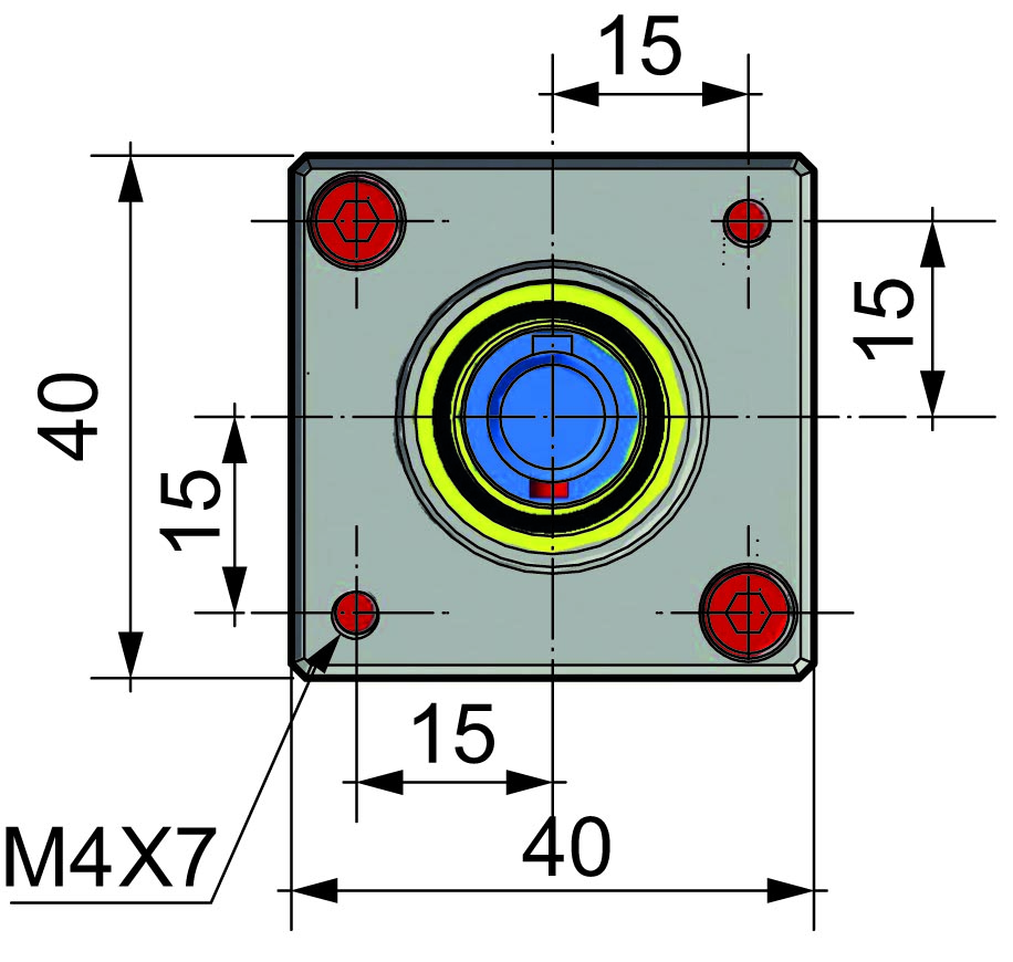
top view |
|
|
 |
|
| RATIOS | ||||||||||||||||||
|
||||||||||||||||||
|
||||||||||||||||||
|
||||||||||||||||||


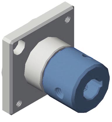
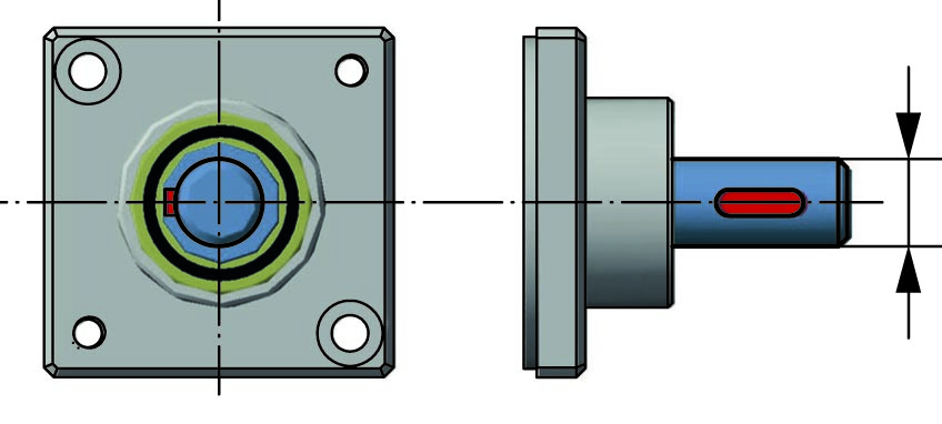
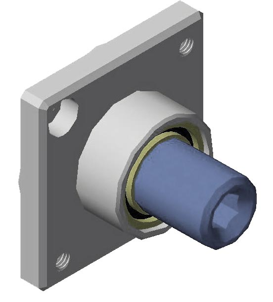
| COUPLINGS | |
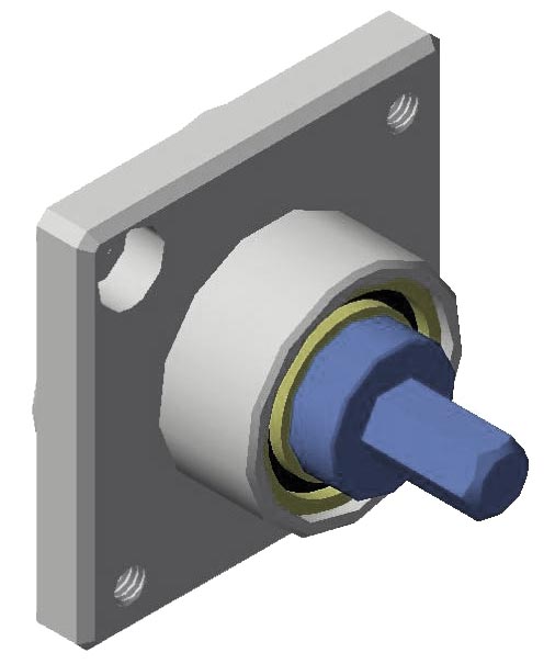
| type ⟪M⟫ | type ⟪F⟫ |
 |
 |
 |
 |
| AVAILABLE SIZES | |
|
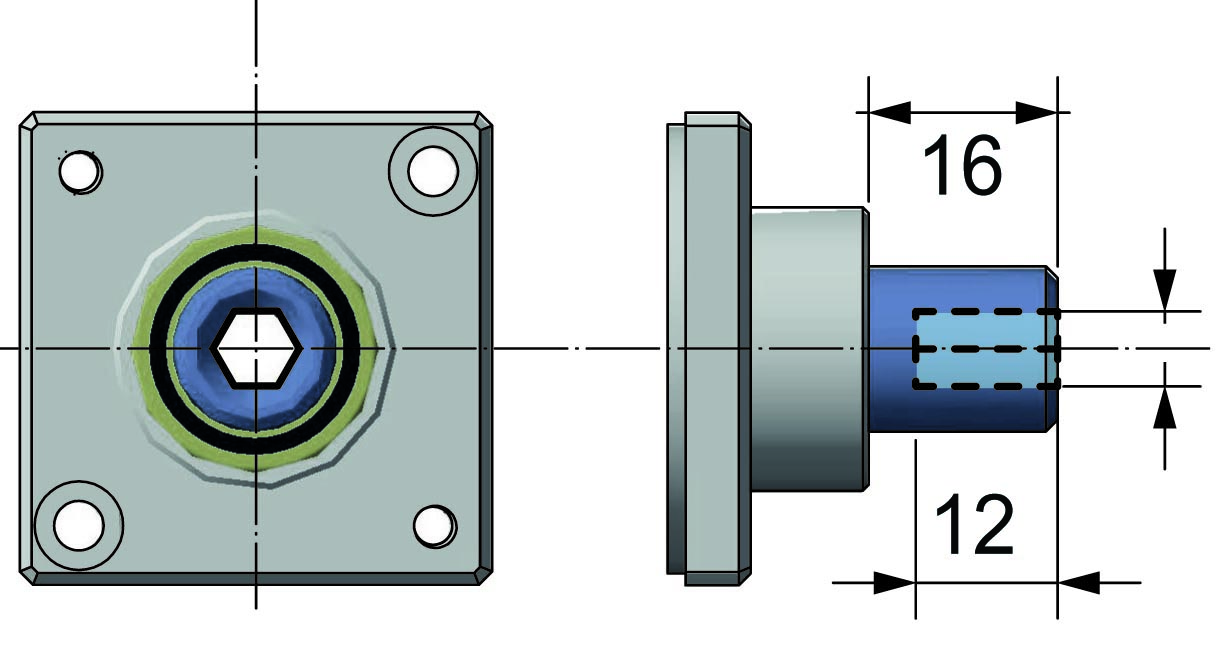
M(Ø06x16 CH2) |
F(Ø06x16 CH2) |
| M(Ø08x16 CH2) | F(Ø08x16 CH2) |
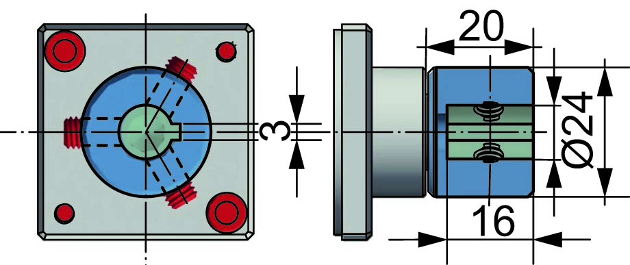
| M(Ø10x20 CH3) | F(Ø10x16 CH3) |
| M(Ø10x25 CH3) | F(Ø12x16 CH4) |
| M(Ø12x20 CH4) | F(Ø14x16 CH5) |
| M(Ø14x20 CH5) | |
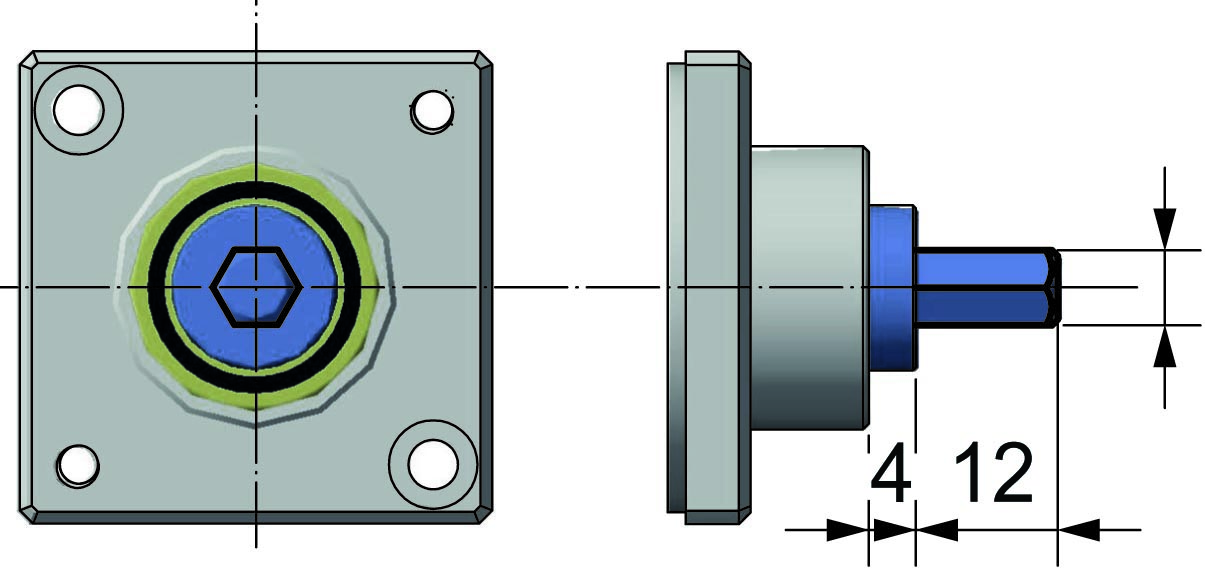
| type ⟪M⟫ (hexagon) | type ⟪F⟫ (hexagon) |
|
|
 |
|
|
 |
|
AVAILABLE SIZES |
|
|
M(Ø6,35x12) |
F(Ø6,35x12) |
| COMBINATIONS OF AVAILABLE COUPLINGS | ||
| RDE40 M-M | RDE40 M-F | RDE40 F-M |
 |
 |
 |
| RDE40 F-F | RDE40 M |
 |
%20F(hex%206,35).jpg) |
|
TECNICAL SPECIFICATIONS |
||
|
Nominal ouput torque |
intermittent continuous |
20 Nm
10 Nm
|
|
Input/ouput radial load |
25 N | |
|
Input/ouput axial load |
1 N | |
|
Max. gearplay |
0,5° | |
|
Weight |
1 stage = ; 2 stages = ; 3 stages = | |
|
Working temperature |
-20° +90° | |
| Lubrication | Intermittent Use - grease: saneg lx ep2 Continuous Use - grease: saneg lx ep2 for speeds ≤ 200 rpm - oil bath: castrol optigear 110/100 for speeds > 200 rpm |
|
|
Working life |
10.000 hours | |
| REPRESENTATION OF REDUCTION RATIO |
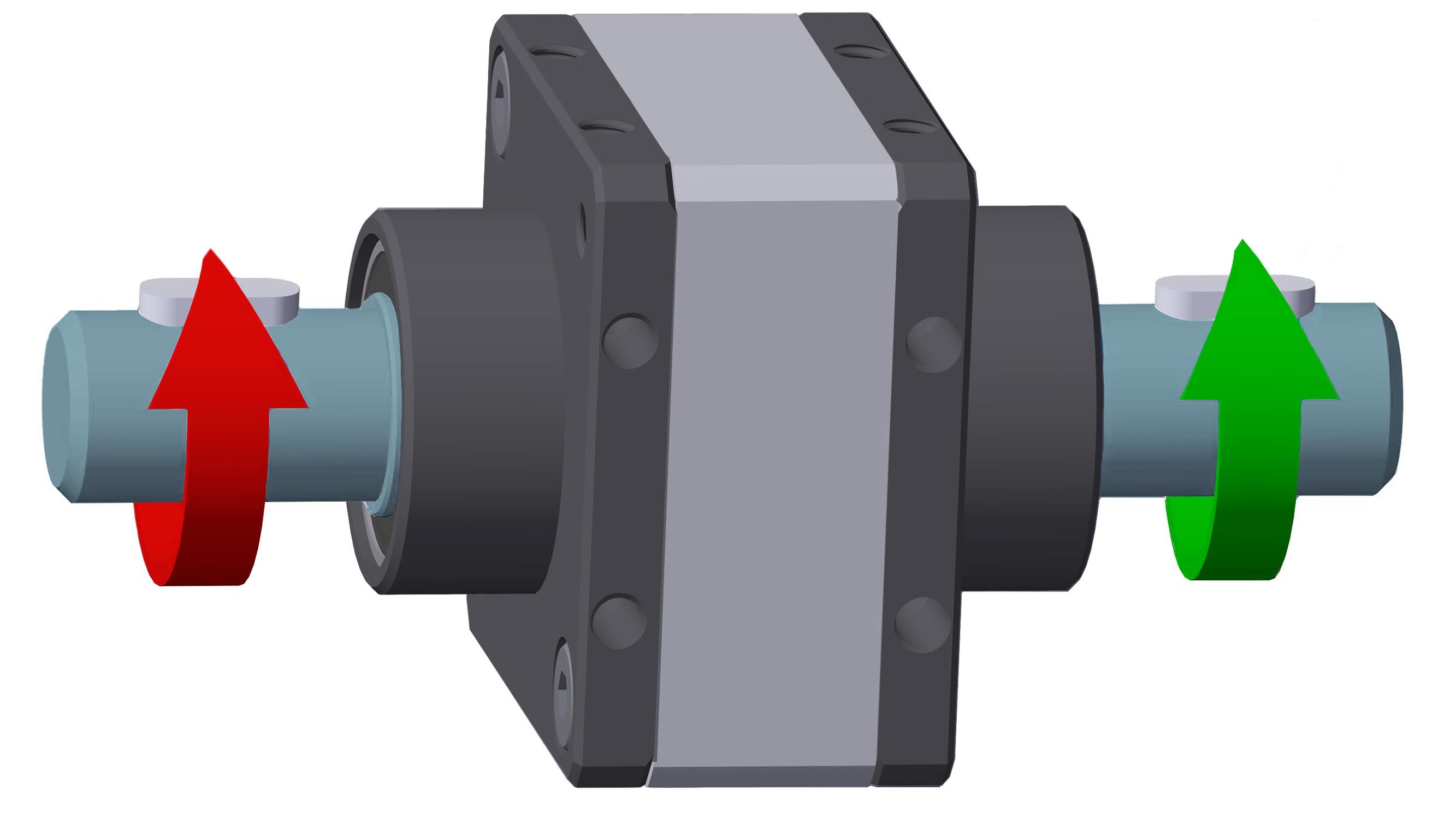 [AV] = fast shaft [AL] = slow shaft |
| 1-STAGE | 2-STAGES | 3-STAGES |
AV= 3 - AL = 1 AV = 4 - AL = 1 AV = 5 - AL = 1 AV = 10 - AL = 1 |
AV = 15 - AL = 1 AV = 20 - AL = 1 AV = 25 - AL = 1 AV = 30 - AL = 1 AV = 40 - AL = 1 AV = 50 - AL = 1 |
AV = 75 - AL = 1 AV = 100 - AL = 1 AV = 125 - AL = 1 AV = 150 - AL = 1 AV = 200 - AL = 1 AV = 250 - AL = 1 |
| The ratio and configuration is determined by always showing the fast shafton the left of the drawing. ☛ when ordering, always indicate the fast shaft [AV] first. |
Richiedi l'accesso
| EFFICIENCY TABLE | ||
| STAGE | RATIO | EFFICIENCY |
| 1s | 3 | 90% |
| 4 | 90% | |
| 5 | 90% | |
| 10 | 90% | |
| 2s | 5 | 81% |
| 20 | 81% | |
| 25 | 81% | |
| 30 | 81% | |
| 40 | 81% | |
| 50 | 81% | |
| 3s | 75 | 73% |
| 100 | 73% | |
| 125 | 73% | |
| 150 | 73% | |
| 200 | 73% | |
| 250 | 73% | |
| PERFORMANCE TABLE | |||
|
⟪INTERMITTENT USE⟫ |
⟪CONTINUOUS USE⟫ | ||
| Input speed (Rpm) |
Ouput torque (Nm) |
Input speed (Rpm) | Ouput torque (Nm) |
| 4000 | 6 | 4000 | 3 |
| 3000 | 8 | 3000 | 4 |
| 2000 | 10 | 2000 | 5 |
| 1000 | 12 | 1000 | 6 |
| 500 | 16 | 500 | 8 |
| 250 | 16 | 250 | 8 |
| 100 | 20 | 100 | 10 |
| 50 | 20 | 50 | 10 |
| 10 | 20 | 10 | 10 |
| grease lubrication | oil lubrication | ||
| For higher torques, contact the technical department | |||


