RD26
Right - Angle gear reducer
Highly compact reducer for various industrial applications, in particular for automation and robotics; applicable also to motors.
• Housing made of anodized aluminium, shafts made of steel with surface hardening treatment (high wear and corrosion resistance).
• Standard transmission ratios: 1/1 - 1/2 - 1/3 - 1/4 - 1/5- 1/7,5 - 1/10 - 1/15 - 1/25 - 1/30
• Several mounting options with protruding / hollow input and output shafts.
• Flanges for direct connection to machine, motors and display with position indicators.
• Available versions:
- RD26 Gear reducer
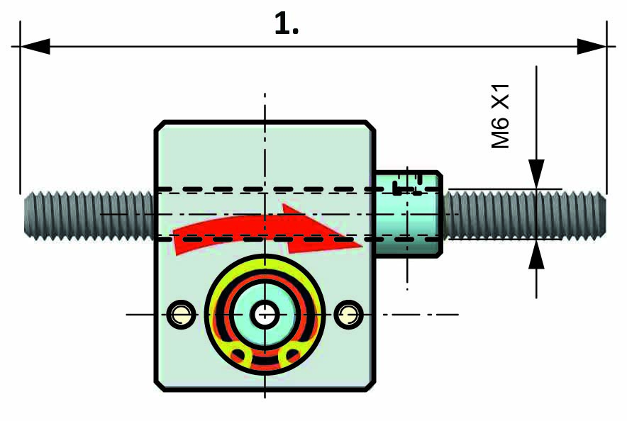
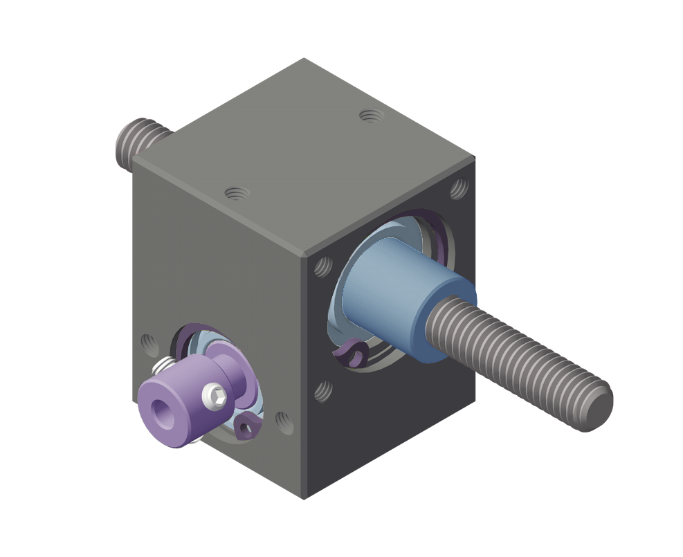
- RD26F for threaded shaft (shaft not supplied)
- RD26S with magnetic sensor
- RD26M with permanent magnet motor
- RD26MS with permanent magnet motor and magnetic sensor
- RD26MR with gearmotor
- RD26MRS with gearmotor and magnetic sensor
➜ For sensor and motor data, see the "General Technical Data" section in the drop-down menu on the right.
|
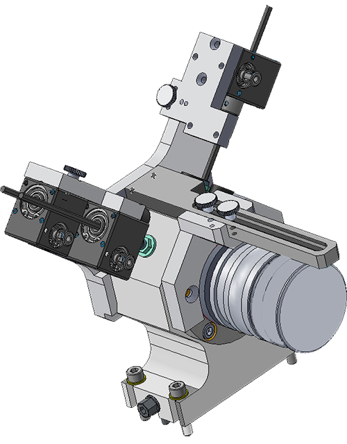
APPLICATION EXAMPLES |
 |
 |
| RD26 |
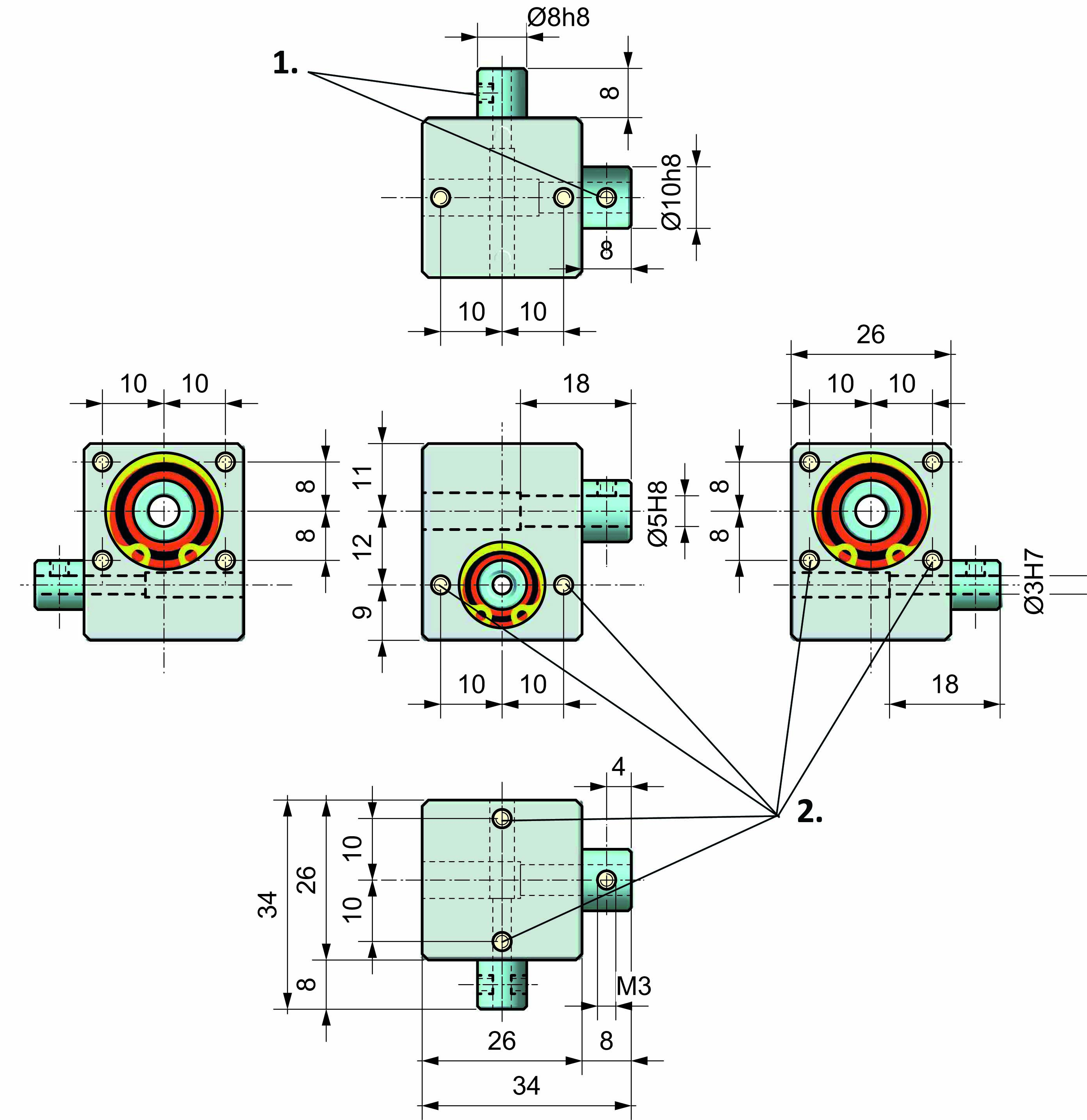 |
| 1. N° 3 shaft lock pins M3 at 120° 2. Threaded M3x6 |
| RD26F for THREADED OUTPUT SHAFT (shaft not supplied) |
 |
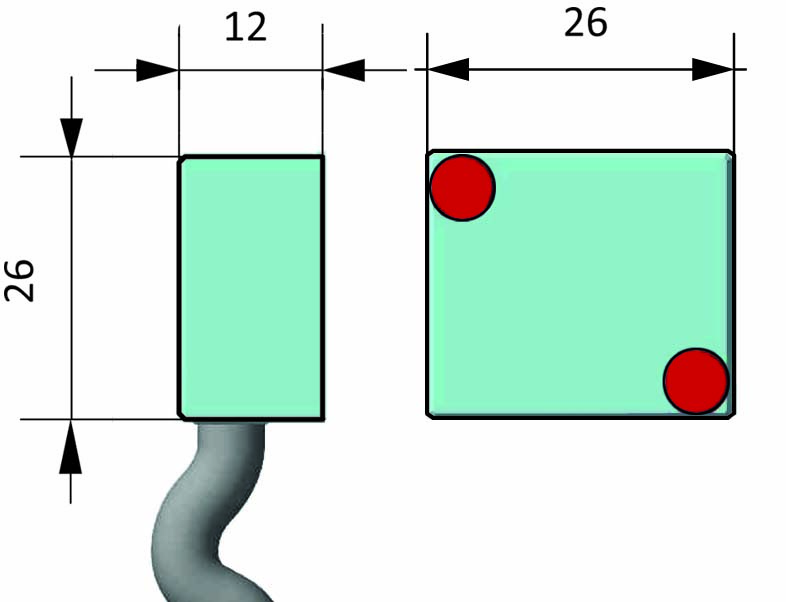
| SENSOR DATA FOR RD26 | |
|
|
|
|
Dimensions |
12 x 26 x 26 cm |
|
Power supply |
10 ÷ 30 Vdc ±10%, max 60 mA |
|
Accuracy |
256 pulses/rev |
|
Max. current ouput |
channels A - B (20mA) |
|
Protection degree |
IP66 |
|
Case |
anodized aluminium |
|
Working temperature |
-10 ÷ 70 °C |
|
Working humidity |
10 ÷90% |
|
Cable output |
0,5 - 1 -2 -5 -10 meters |
|
EMC |
2004/108/CE |
|
The sensor converts the rotation output shaft of the gearbox |
|
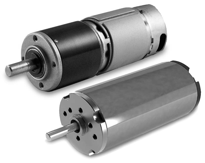
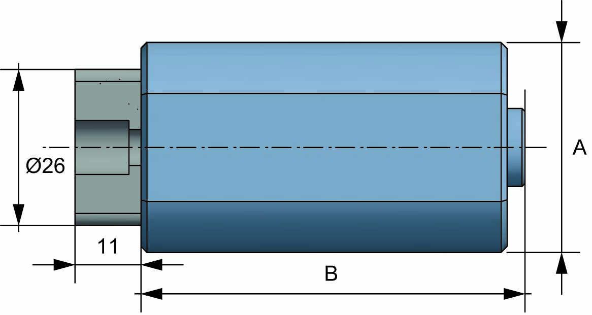
| MOTORS FOR RD26 | |
 |
 |
|
MOTORS "M" WITH COUPLING FOR RD26 |
GEARMOTORS "MR" WITH COUPLING FOR RD26 | ||||||
| A | B | RPM | TORQUE (Nm) | A | B | RPM | TORQUE (Nm) |
| 35 | 56 | 2200 | 0,06 | 30 | 79 | 450 | 0,4 |
| 35 | 65 | 11000 | 0,05 | ||||
|
➜ suitable for alternate movements |
➜ suitable for continuous movements |
||||||
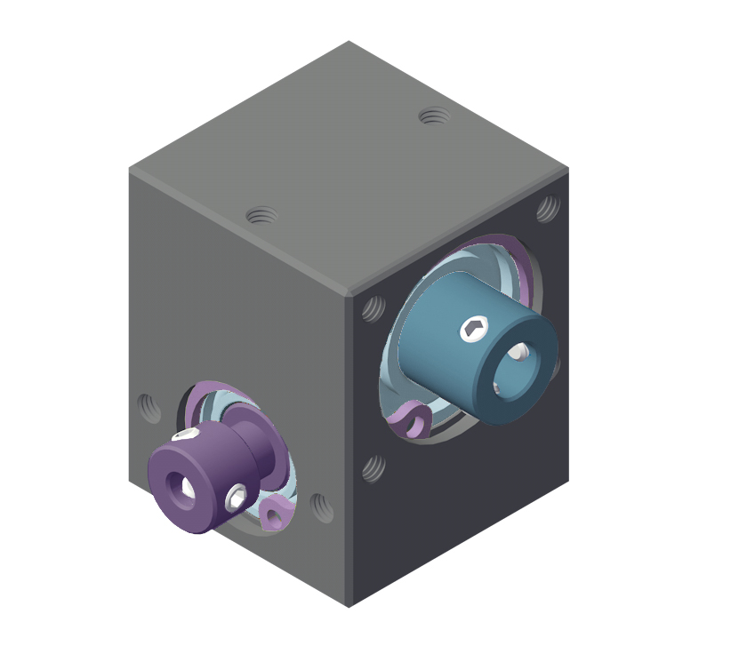
| AVAILABLE VERSIONS | ||
| RD26 reducer | RD26F for threaded shaft | RD26S with sensor |
 |
 |
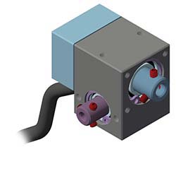 |
| RD26M with motor | RD26MR with gearmotor | |
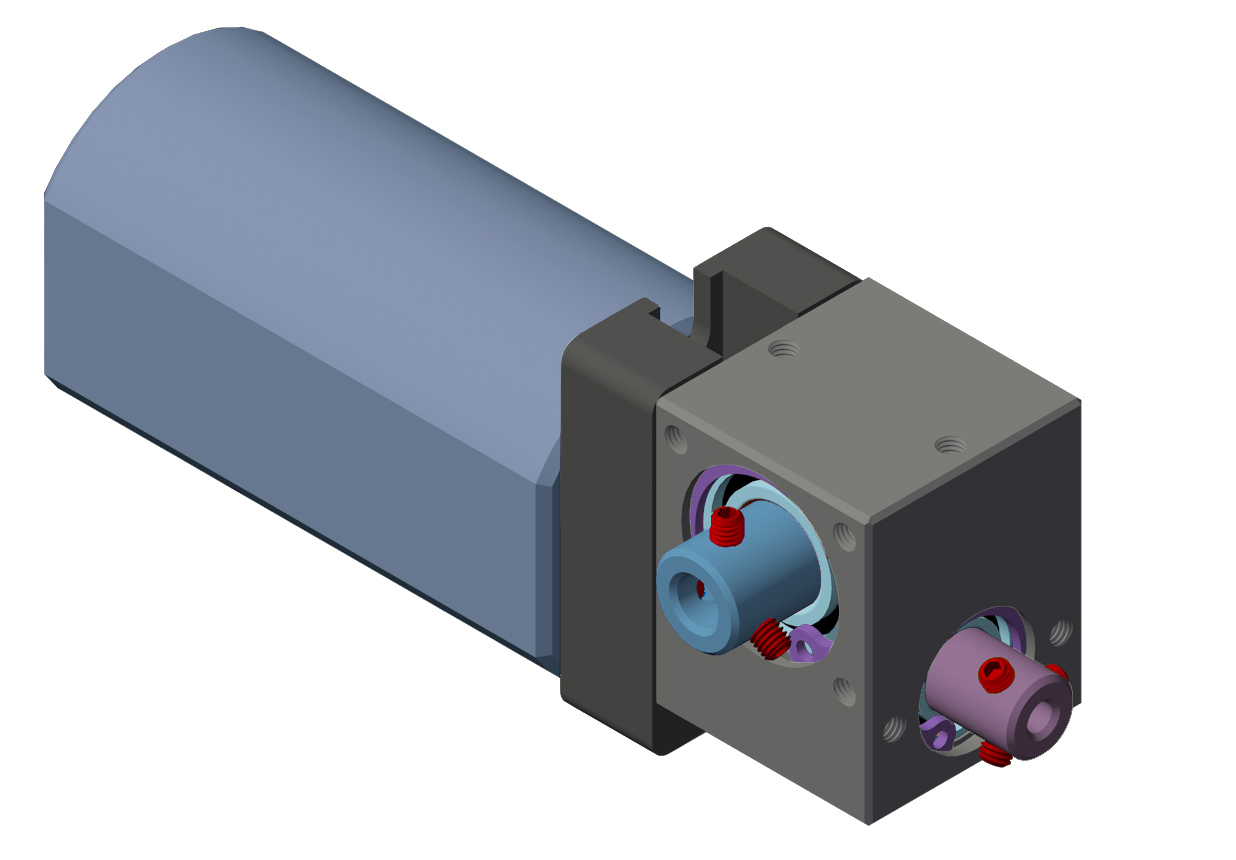 |
 |
|
| RD26MS with motor & sensor | RD26MRS with gearmotor & sensor | |
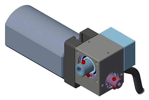 |
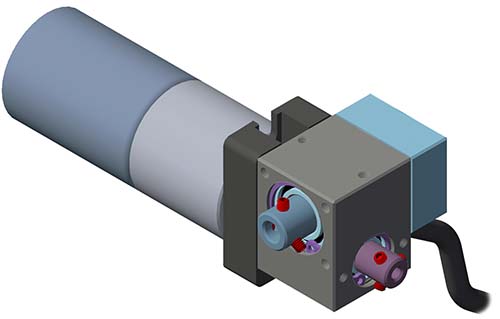 |
|
Richiedi l'accesso
| TECHNICAL FEATURES | |
| FA = input axial load | 20 N |
| FA = ouput axial load | 20 N |
| FR = input radial load | 100 N |
| FR = output radial load | 200N |
| Max. backlash | 0,75° |
| Max input rpm (1/min) | 5.000 |
| Working temperature | -20 +90° |
| Life | 10.000 h |
| Weight | 80 gr |
| Lubrication | grease Klüber AG 11-462 |
| EFFICIENCY TABLE |
| i | 1/1 | 1/2 | 1/3 | 1/4 | 1/5 | 1/7,5 | 1/10 | 1/12,5 | 1/15 | 1/25 | 1/30 |
| R % | 0,72 | 0,72 | 0,69 | 0,63 | 0,60 | 0,61 | 0,55 | 0,39✽ | 0,45✽ | 0,25✽ | 0,30✽ |
|
TI Nm |
4,18 | 2,07 | 1,46 | 1,19 | 1 | 0,66 | 0,55 | 0,61 | 0,44 | 0,48 | 0,34 |
| TO Nm | 3 | 3 | 3 | 3 | 3 | 3 | 3 | 3 | 3 | 3 | 3 |
✽ irreversibility
| Legend: |
| i = transmission ratio |
| R = efficiency |
| TI = input torque |
| TO = output torque |
➜ In case of continuous use, please contact our Technical Dept. In such applications, a grease fitting will be installed to allow periodic addition of lubricant with a frequency based on the work conditions.
⁃ To identify the most suitable gear reducer for your requirements, refer to the values in the table. If the real loads and efficiency are very close to the table values, contact the technical department.
⁃ All tables show linear measurements expressed in <mm>, unless otherwise specified.
⁃ All the reduction ratios are expressed as a <fraction> unless otherwise specified.
⁃ All forces, efficiency and the loads are expressed in <N or Nm> (10 N ≅ 1 kg or 10Nm ≅ 1Kgm ) unless otherwise specified.


